The PTek FM500ES (and other “ES” series PTek transmitters) uses two different logic pins for turning the transmitter’s RF power on or off; however, many monitoring and control devices such as silence detectors, RF loss sensors, etc. only utilize a single output pin to indicate either the “alarm” or “normal” status by controlling whether or not that pin is pulled low (to ground potential.) I have a client using both an Inovonics Novia 272 Audio Processor and an Inovonics 674 AM Monitor Receiver at the site of an FM Translator. This created a bit more challenging application than some transmitters which use a single pin to control the transmitter’s RF on/off status (if the single control pin is at logic “high” (or floating high) the RF is turned on, and if it’s “low” the RF is off.) In those transmitter’s, if an alarm device pulls the pin low (alarm condition) the RF thus shuts down, and when the alarms state clears and the alarm device’s pin goes back to “high” the transmitter’s RF automatically turns back on. Things aren’t quite that simply with the PTek FM500ES (and some of their other transmitters) so I had to devise this workaround.
In keeping with FCC regulations for FM translators, the FM transmitter must have a mechanism for automatically shutting off the RF of the translator FM transmitter if either of the following occurs:
(1) The parent station’s AM transmitter is off-air
(2) Loss of STL/audio source
For this client’s application, we want to use the Inovonics AM 674 Monitor to trigger an alarm if it senses loss of carrier (or audio) from the AM transmitter. We also want to use an alarm contact on the Inovonics Novia 272 Audio Processor to trigger an alarm if it is not receiving audio via its Barix AoIP STL source for some reason (studio not sending audio, ISP/Internet link failure, etc.) So I first needed to devise a logic device which would sense either (or both) of the above described alarms being triggered and in turn pull the “Shut Down” logic pin on the PTEK FM500ES transmitter to logic low state, thus automatically shutting its RF off. Achieving that goal was relatively easy; however, I had to also devise a way to pull a different input logic pin on the PTek to low state in order to make it turn its RF on again.
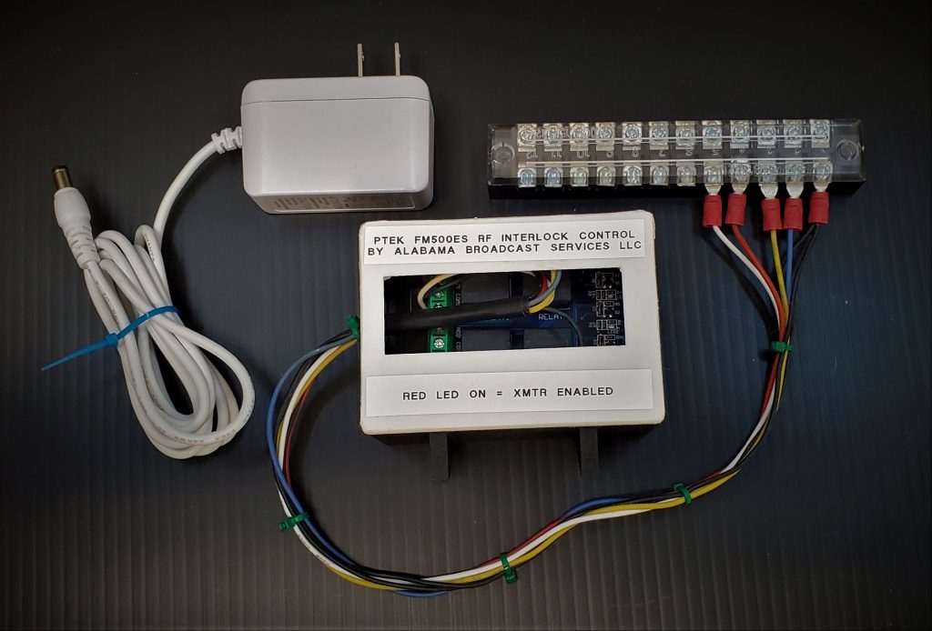
The solution I came up with turned out to be fairly simple. It utilizes an Arduino Uno controller equipped with a relay “shield” (board) attached to it. Both devices are relatively inexpensive — the two devices along with a DC power supply is around $25 (possibly less with careful shopping and use of a comparable Arduino Uno R3 “knock-off.”)
In the following photo, the combination of the Arduino Uno R3 and the Relay Shield were wired up on the lab bench while I was writing and tweaking the code to upload to the Arduino to handle and process the necessary logic functions.
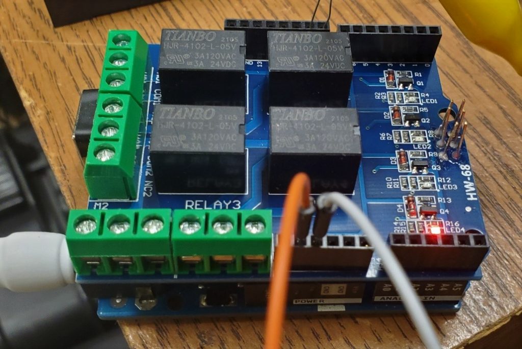
It only took about 30 minutes to develop and upload the necessary Arduino code, commonly referred to in the Arduino world as a “sketch.” The way the sketch works is basically as follows:
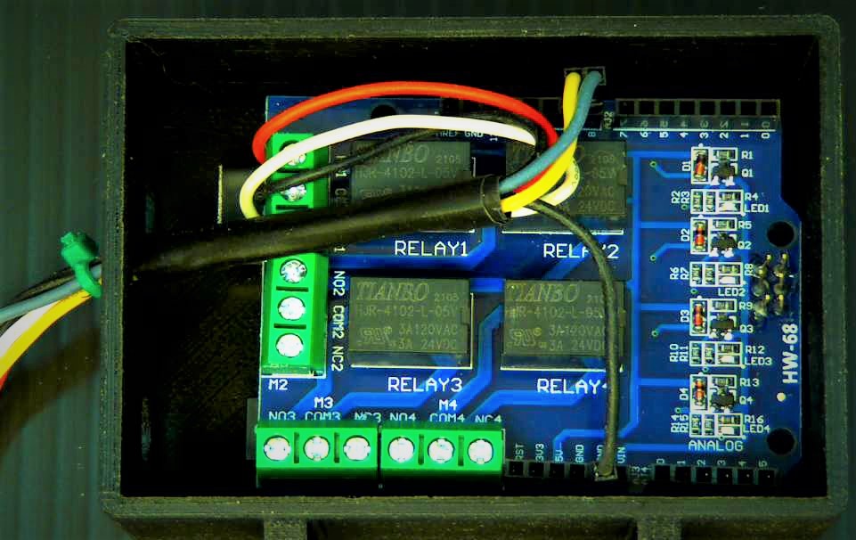
BOTH ALARM MONITORING INPUTS HIGH = NORMAL and relay #1 on the Relay Shield is activated. That means that the Normally Open (NO) contact of the relay is connected to Common (COM) which is wired to ground (GND). That Normally Open (NO) terminal on the relay is in turn wired to the PTek transmitter’s “Start” logic pin. Thus, when things are normal (both audio and RF carrier from the parent station’s AM transmitter are present) the PTek FM transmitter is transmitting.
EITHER OR BOTH ALARM INPUTS LOW = ALARM and the Arduino in turn deactives the relay. When that happens, the Normally Closed (NC) terminal on the relay is connected to the relay’s Common (COM) terminal (instead of the NO terminal.) The relay’s NC terminal is wired to the PTek transmitter’s “Shutdown” logic pin. As a result, the PTek turns off its RF output (goes into its “standby” mode) if there’s a loss of RF from the parent AM transmitter or loss of audio. Triggering of both alarms conditions at the same time is similarly considered an alarm state by the Arduino Uno so the transmitter’s RF is turned off in that state as well.
When things return to normal, the Arduino turns around and activates the relay, flipping back to the NO-to-COM connection, pulling the PTek’s “Start” function pin low again, so the transmitter RF turns on again.
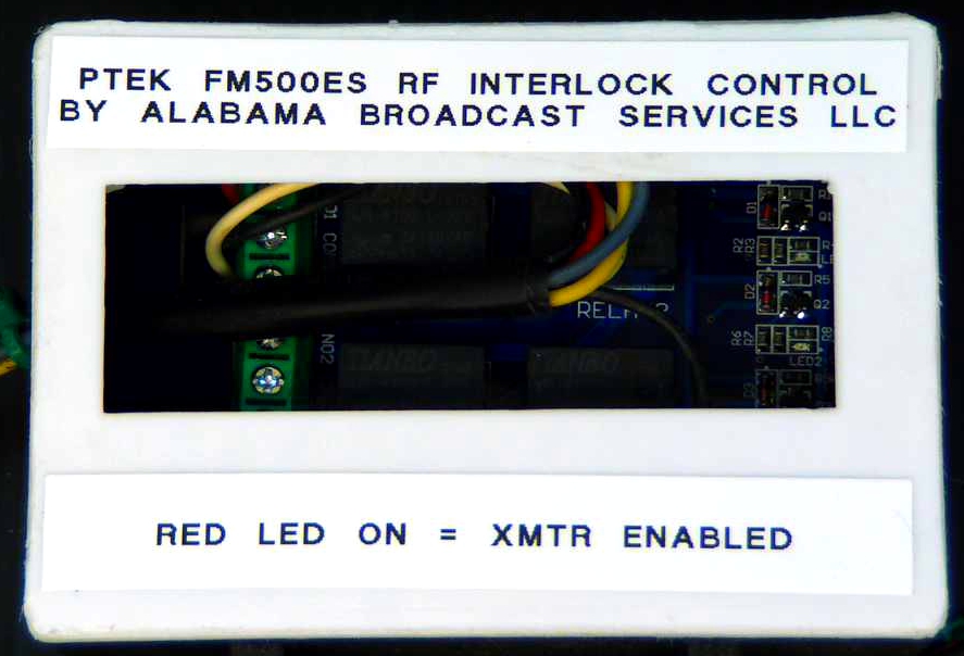
I chose to use the “active” state and the NO-to-COM relay connection for turning the transmitter’s RF on (as opposed to using the NC-COM connection and only powering the relay’s coil during alarm conditions) for a specific reason: should the Arduino Uno or the relay ever fail, the FM transmitter will automatically shut down. This will alert me, as their engineer, that something is wrong with the control circuitry so that I can go to the site and investigate. During the controller failure situation, the transmitter can’t accidentally transmit a silent carrier or transmit while the parent AM transmitter is off-air, either of which would be a “no-no” with the FCC. While working at the translator site, I can re-enable the transmitter during the controller repair by simply unplugging the logic/control interface cable from the rear of PTek transmitter and press the PTek’s “Start” button. As long as I’m physically at the transmitter and listening to make sure the AM transmitter is on the air and there’s audio to both transmitters, manual operator control is okay with the FCC. I keep a stack of Arduino Uno boards on-hand and connecting one to the laptop in order to upload the necessary code to it to turn it into a replacement for this logic controller takes only a couple of minutes to complete.
Using the Relay Shield with four relays instead of something with only one relay has its advantages in terms of expansion capability and emergency repairs should the relay fail: by quickly moving the three wires hooked to the failed relay and changing one digit in the Arduino’s program/code (the number of the digital pin on the board corresponding to which relay is being utilized) the relay is replaced with another working one in just a moment.
Having four relays available — along with many other digital and analog input and output pins on the Arduino Uno — means that adding some other features, functions, etc. in the future is possible. I have added tower light status and alarm monitoring to Arduino Uno’s and its bigger brother (the Arduino Mega 2560), along with temperature monitoring and triggers for shutting down the transmitter in a seriously overheated transmitter room), ethernet “shields” (boards which plug onto the Arduino which facilitate network and internet accessibility, control, and communications) to monitor other things such as feedline pressures, power failures, etc. The possibilities are really only limited by the imagination.